
Wiring a ceiling fan isn’t rocket science, but one wrong connection can mean a fan that won’t spin, a light that won’t turn on, or worse, a tripped breaker or damaged wiring. Whether you’re replacing an old fixture or running a fresh install, having a clear ceiling fan wiring diagram in front of you makes the difference between a smooth job and a frustrating one. At Fenelon Handyman Services, we’ve wired and installed ceiling fans across Tampa homes since 2014, and we know firsthand that most wiring mistakes come from misidentifying just one or two wires.
The challenge is that ceiling fan wiring isn’t one-size-fits-all. You might have a single switch controlling both the fan and light, dual switches with separate controls, or a remote receiver adding extra wires into the mix. Wire colors can also vary between manufacturers, and older Tampa homes sometimes have wiring that doesn’t follow modern color conventions at all. Understanding what each wire does, and where it connects, is exactly what a good wiring diagram shows you.
This guide breaks down the most common ceiling fan wiring diagrams you’ll encounter, covering standard wire color codes, single-switch and dual-switch setups, remote control configurations, and capacitor wiring. We’ll walk through each diagram so you can identify your specific situation and wire your fan correctly. And if you reach a point where the wiring looks unfamiliar or you’d rather have a licensed professional handle the electrical work, our team at Fenelon Handyman Services is always ready to help homeowners across the Tampa area.
Safety and prep before you touch any wires
Before you pull out a ceiling fan wiring diagram and start connecting wires, you need to make the work area safe. Electrical work at the ceiling level carries real risks, including live wires, unexpected wire configurations, and junction boxes not built to handle a fan’s weight. Taking 15 to 20 minutes on prep before you touch anything protects both you and your home’s electrical system from problems that are entirely avoidable.
Skipping the power shutoff is the single most common cause of electrical injuries during DIY fan installs.
Turn off the right breaker
Your first move is to locate your electrical panel and shut off the breaker that controls the ceiling fan circuit. Don’t just flip the wall switch and assume the power is off. The switch cuts power to the fan, but the wires inside the junction box can still carry live current. Go to your breaker panel, identify the correct breaker, and switch it off. If your panel isn’t labeled clearly, flip breakers one at a time and use a non-contact voltage tester at the switch or outlet to confirm which one controls the room.
After switching off the breaker, bring your non-contact voltage tester up to the junction box and hold it near each wire individually. No beep or light from the tester means no live current, and only at that point is it safe to proceed with the install.
Tools and materials to have ready
Having the right tools at hand before you climb the ladder keeps the job clean and prevents costly mistakes. Gather these items before you start:
- Non-contact voltage tester (essential for confirming the power is actually off)
- Flathead and Phillips screwdrivers
- Wire strippers and needle-nose pliers
- Electrical tape and wire nuts (often included with the fan, but have extras on hand)
- A phone or tablet to photograph the existing wiring before you disconnect anything
That last item matters more than most people expect. Snapping a picture of how the original wires were connected gives you a clear reference point if you get confused mid-install, and it takes about five seconds to do.
Inspect the junction box
Your ceiling junction box must be rated for fan support, not just a standard light fixture box. Fan-rated boxes are built to handle the weight and constant motion of a spinning fan. Standard boxes can work loose over time, which creates a wobbling fan and a genuine safety hazard. Look for the phrase "Acceptable for Fan Support" stamped or printed inside the box before you mount anything to it.
Confirm the box is also securely anchored to a ceiling joist or a fan-rated brace bar. Push on it firmly with your hand. Any movement at all means you need to replace or reinforce it before the fan goes up. In older Tampa homes especially, many fixtures were originally mounted with standard light boxes long before fan-rated box requirements became standard practice.
Wire colors and what each one usually means
Before you match any wires in your ceiling fan wiring diagram, you need to know what each color signals in the first place. Wire colors follow conventions set by the National Electrical Code (NEC), but ceiling fans add a few extra wires beyond what you’d find in a standard light fixture. Getting these colors right before you make a single connection saves you from a frustrating troubleshooting session after everything is back together.
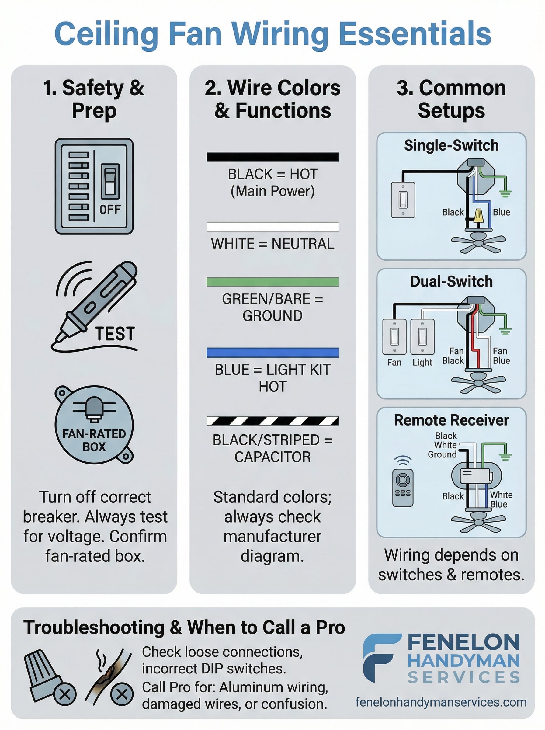
Standard house wiring colors
The wires coming out of your ceiling junction box follow a straightforward system. Black is your hot wire, carrying live current from the switch to the fixture. White is your neutral wire, completing the circuit back to the panel. Bare copper or green is your ground wire, which gives fault current a safe path if something goes wrong. In older Tampa homes, you may occasionally find white wires wrapped with black electrical tape, which means a previous electrician re-coded that wire to indicate it functions as a hot wire in that specific run.
Never assume a white wire is neutral until you’ve confirmed the power is off and verified it with a non-contact voltage tester.
The extra wires ceiling fans add
Ceiling fans introduce one or two additional wires that a standard light fixture doesn’t have. Blue is the most important one, and it carries power specifically to the light kit. When your fan includes a separate light, the blue wire connects to the black wire from the ceiling’s light circuit. Some fans also include a striped wire (usually black with a white stripe) that connects to the capacitor, which regulates fan speed. Here’s a quick reference for all the wire colors you’re likely to encounter:
| Wire Color | Function |
|---|---|
| Black | Hot (main power) |
| White | Neutral |
| Green / Bare copper | Ground |
| Blue | Light kit hot |
| Black/white stripe | Capacitor or speed control |
Manufacturers don’t always stick to these conventions exactly, so always check the wiring diagram included with your specific fan model before you start connecting wires.
Wiring diagrams by switch setup
Your specific wiring diagram depends almost entirely on how many switches control the fan. The physical wire connections at the ceiling change based on whether you have one switch running everything or two separate switches giving you independent control over the fan and light. Identifying your switch setup before you touch a single wire is the fastest way to find the right configuration and avoid connecting wires to the wrong terminals.
Single-switch setup
A single-switch setup means one wall switch controls both the fan motor and the light kit at the same time. In this configuration, your ceiling junction box typically has one black (hot) wire and one white (neutral) coming from the switch. At the fan, you connect the black ceiling wire to both the black fan wire and the blue light wire together, using a single wire nut to join all three. Connect white to white, and ground to ground.
This is the most common setup in Tampa homes that originally had a light fixture and were later converted to a ceiling fan.
Here’s how those connections line up:
| Ceiling wire | Fan wire(s) | Notes |
|---|---|---|
| Black (hot) | Black + Blue | Join all three with one wire nut |
| White (neutral) | White | Connect directly |
| Bare/Green (ground) | Green or bare | Connect directly |
Dual-switch setup
A dual-switch setup gives you separate wall controls for the fan speed and the light, which requires a cable with two hot wires running from the switch box to the ceiling. In this configuration, you’ll typically find a black wire and a red wire alongside the white neutral in the junction box. Connect black to the fan’s black wire and red to the fan’s blue wire. This ceiling fan wiring diagram setup is more involved, but it gives you the most flexibility once everything is connected.
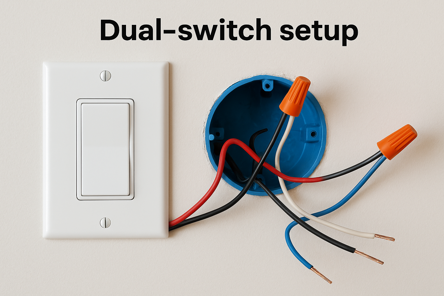
Your junction box must have a two-conductor cable plus ground (14/3 or 12/3) running from the switch for this setup to work. If you only see a single black and white wire in the box, you’re working with a single-switch run and would need to run new cable to support dual switches.
Remote receivers and smart controls
A remote receiver adds a third layer of wiring inside your fan canopy, sitting between the ceiling wires and the fan’s internal connections. Before you follow any ceiling fan wiring diagram for a remote setup, understand that the receiver has its own wire leads coming in from the ceiling and going out to the fan. Power comes into the receiver from the ceiling, and the receiver then sends separate outputs to the fan motor and light kit. This is why the wire count inside the canopy feels higher than expected.
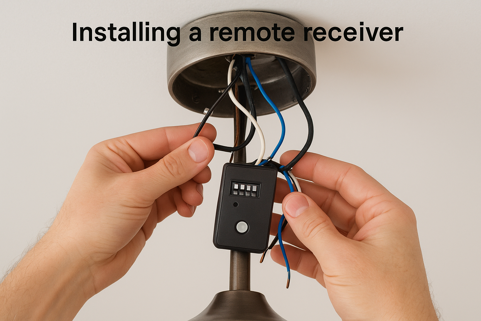
Installing a remote receiver
Most remote receivers include a DIP switch or frequency dial that needs to match the handheld remote before the unit works. Set the receiver and remote to the same channel first, before you install anything. Then follow these connections:
| Ceiling wire | Receiver input | Notes |
|---|---|---|
| Black (hot) | Black input | Live power into receiver |
| White (neutral) | White input | Neutral into receiver |
| Ground | Ground | Connect directly to fan |
From the receiver’s output side, connect the receiver’s black output to the fan’s black wire, and the receiver’s blue output to the fan’s blue (light kit) wire. Tuck the receiver into the canopy before mounting the fan to the ceiling bracket.
Smart controls and Wi-Fi adapters
Smart ceiling fan adapters, such as those compatible with Amazon Alexa or Google Home, install in the same canopy location as a standard remote receiver. The wiring connections follow the same input/output pattern described above. However, most smart adapters also require a neutral wire at the canopy to function, so confirm your junction box has one before purchasing a smart module.
If your existing wiring has no neutral wire in the canopy, a smart adapter will not work without running new cable.
Some smart modules also require a 2.4 GHz Wi-Fi network nearby for reliable connection during setup, so have your phone and network credentials ready when you power the circuit back on.
Troubleshooting and when to call a pro
Even with a solid ceiling fan wiring diagram in hand, problems can show up after installation. Before you assume something is wrong with the fan itself, work through the electrical connections first. Most post-install issues trace back to a loose wire nut, a missed connection, or a wire pulled out of contact when the canopy was tightened against the ceiling.
Common wiring problems and fixes
Start your troubleshooting by turning the breaker back off and pulling the canopy down to inspect every connection. Here are the most frequent problems and what causes them:
| Symptom | Likely cause | Fix |
|---|---|---|
| Fan doesn’t spin, light works | Black fan wire not connected | Re-join black ceiling wire to fan’s black wire |
| Light doesn’t work, fan spins | Blue wire disconnected | Re-join blue wire to hot source |
| Neither fan nor light works | Breaker tripped or loose wire nut | Check panel first, then inspect all wire nuts |
| Fan hums but won’t spin | Capacitor wire loose or failed | Check black/white striped wire connection |
| Remote unresponsive | DIP switch mismatch | Reset receiver and remote to matching channel |
After re-seating any loose connections, restore power at the breaker and test each function before you button the canopy back up. Testing with the canopy open saves you another trip up the ladder.
When to call a licensed electrician
Some situations go beyond what a wiring diagram and a set of wire nuts can fix. Call a licensed professional if you open the junction box and find aluminum wiring, which is common in Tampa homes built between the 1960s and mid-1970s and requires special handling to connect safely to modern fixtures. You should also stop and call if you find more than four wires in the box with no clear labeling, scorched insulation on any wire, or a junction box that moves when you press on it.
Working with damaged or unknown wiring without professional guidance creates fire and shock risks that no DIY savings are worth.
Fenelon Handyman Services handles ceiling fan wiring across Tampa, and our team can identify unfamiliar configurations quickly and wire your fan correctly the first time.
Wrap-up and what to do next
A solid ceiling fan wiring diagram gives you the roadmap you need to connect your fan correctly, whether you’re working with a single switch, dual switches, or a remote receiver. The key steps are always the same: cut power at the breaker, verify it with a voltage tester, identify your wire colors, match them to the right configuration for your setup, and test everything before closing up the canopy. Handle aluminum wiring, scorched insulation, or unlabeled wires by calling a professional rather than guessing.
If your junction box is undersized, your wiring looks unfamiliar, or you simply want the job done right without climbing a ladder, the team at Fenelon Handyman Services is ready to help. We’ve installed and wired ceiling fans in Tampa homes since 2014, and we bring the same attention to detail to every job. Contact Fenelon Handyman Services to schedule your ceiling fan installation today.